When celebrating four birthdays at once, use LEDs to avoid lighting 175 candles.
Birthday LED Candles
July 2016
Contents
For More on this Project
In July of 2016 my family celebrated some significant birthdays. Two of them were major jubilees: my uncle Jüri turned 80 and my cousin Torm marked 50. Since cousin Kia also celebrated 39 in the same month and Torm's daughter Sofia reached the serious age of 6 at very nearly the same time, we planned one large combined party in Connecticut at the home of my uncle. But birthdays mean candles, and 175 candles is a lot of firepower.
Design
Part of the “design brief” issued by my aunt was the idea that the effect should be circular in some way. I also wanted to the design to be a good fit with the house and the surroundings. Estonian cultural references are always nice to include in family projects when I can. Finally, it would be nice if whatever products I make could come together in some combined display but would also be separable so that each birthday kid could keep their own, as my gift. I started sketching.
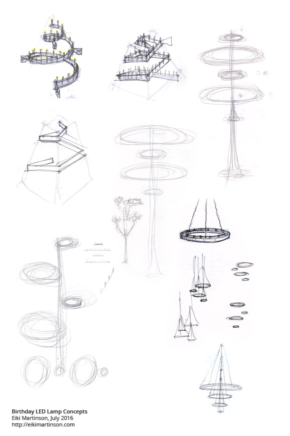
Progress of design ideas. Fanciful!
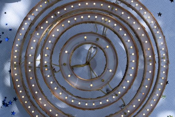
I settled on a design with four concentric stacked rings, bearing 6, 39, 50, and 80 LEDs each. Those LEDs (sourced from Evil Mad Scientist and made by Betlux Electronics) are standard-sized 5mm through-hole LEDs, warm-white in color, with a candle-flicker effect built in—that is, you can bias them in the normal way with a dropping resistor and an internal circuit takes care of the rest. With a forward voltage of 2.7V, I would drive each lamp with its own 3.3V power supply (so that they would be individually switchable and could be taken home separately) and each LED would get its own resistor. Sharp-eyed students of the color code will notice that they are 30.1 ohm resistors with 1% tolerance (such precision is unnecessary but they were cheap anyway), giving us a current of 19.9 mA through each LED.
I decided to make the top and bottom plates of each lamp out of frosted acrylic using the FSL 40W laser cutter, which would accurately cut the profile and cut 175 5mm holes to boot. As usual I experimented a bit first, trying some test cuts with slightly smaller and slightly larger holes to make sure I got a reliable friction fit that would hold the LED reasonably tightly while I built the circuit around it. The laser I'm working with has a 20 inch by 12 inch working area, so I had to design the two larger-diameter rings, for 50 and 80 LEDs, in segments that I would later glue together. I experimented with puzzle-piece joints between the two but found that to be unnecessary; solvent bonding a simple butt joint with acrylic cement was perfect.
Circuit Construction
Although often the messy result of a lazy approach, “free-form” or “point-to-point” circuit construction techniques, done with care, can look really cool. I admire that style when I see particularly lovely examples of it. So I bought bare copper wire and after some experimentation was able to form pretty accurate circles by hand, progressively taping the circle to the acrylic ring, which served as a guide, with masking tape. Each lamp has two rings, an inner and outer one, that carry power and ground to each LED and resistor combination. I connected the rings themselves via solder joints to brass standoffs, which also serve to structurally separate the top and bottom acrylic lids. Those lids received some countersunk holes for 6-32 brass screws (either three or six, depending on the size of the lamp) that connect everything together.
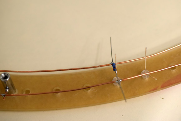
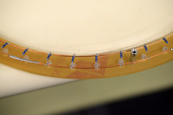
Although it looks like the resistor is soldered in three places, which would short the LED, the resistor's lead is only resting on the outer ring.
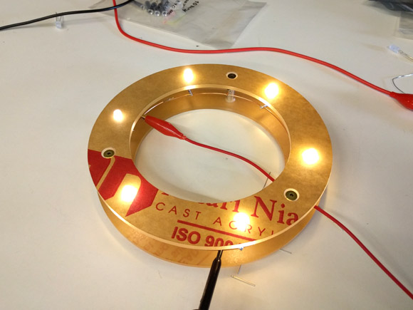
Assembled and powered circuit for the six LED lamp
Inner and outer rings in position
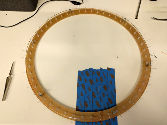
An outer ring soldered to the LEDs
I started with the six LED lamp to prove the technique and get some practice and went up from there. Eventually I evolved a method in which I pre-bent all the LED leads, inserted them into the acrylic top, rested the outer copper ring on those leads, and went around the ring soldering those joints.
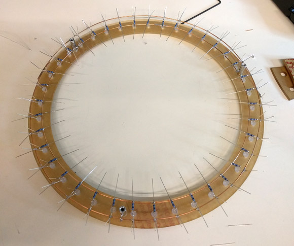
Resistors and inner ring soldered
Test early, test often.
Next I'd position resistors, using a combination of gravity, spring tension from the resistor leads, movable weights, and so forth to hold them in place long enough to get them soldered to each LED and to the inner ring. Then I'd go around clipping the resistor lead that rested on the outer ring so that I could apply power and check on my work so far.
Flush cut LED and resistor branches
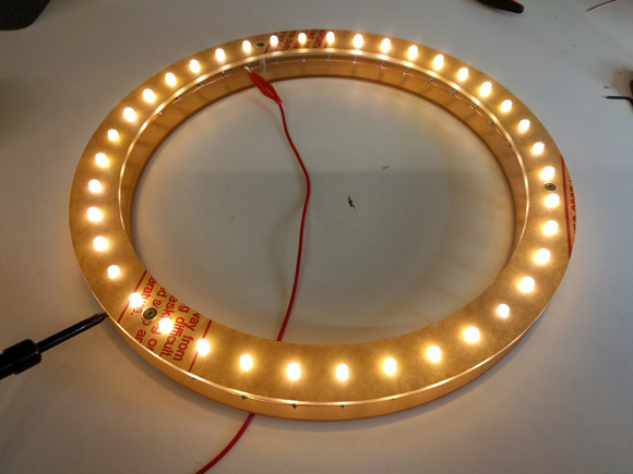
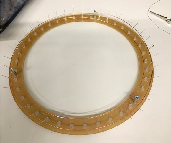
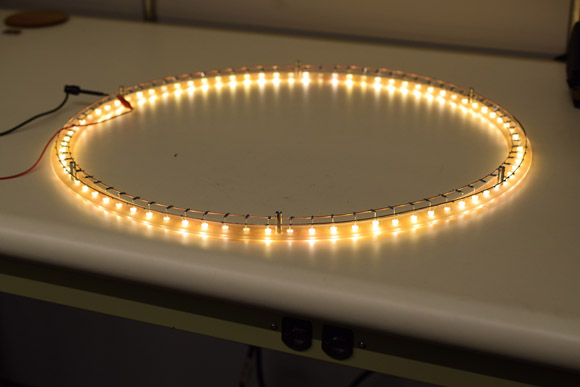
An assembled and powered 39-LED ring
With the ring lighting up as it should, I proceeded around it again clipping the rest of the leads short before powering another time to make sure nothing came loose—that's a lot of solder joints after all!
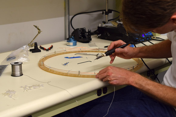
Making a start on the largest ring
For the largest lamp I completed a few LED and resistor branches around the ring to hold everything together structurally before populating the rest of the LEDs.
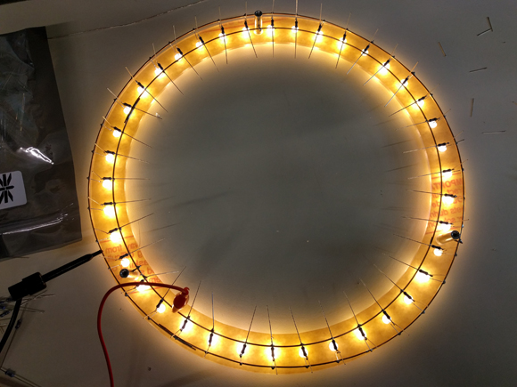
The 80 LED ring merrily twinkling. A cheering sight after so much work!
Brass Feet
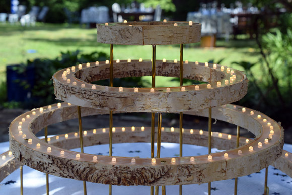
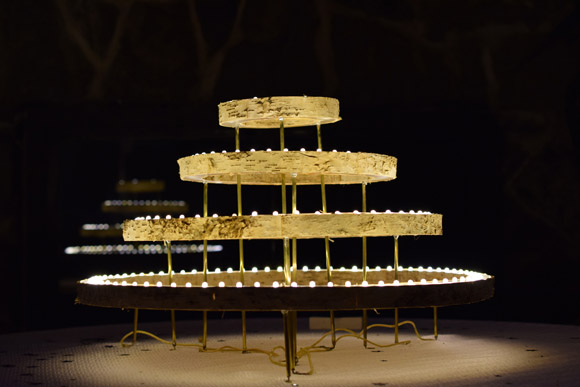
To separate the concentric lamps from each other visually I wanted to raise them at varying heights so that, when assembled, they look like a tiered birthday cake, with the 60-LED lamp the highest, and the 80-LED lamp the lowest. I decided to raise them on three brass legs each, and to carry power to the circuits through the legs directly.
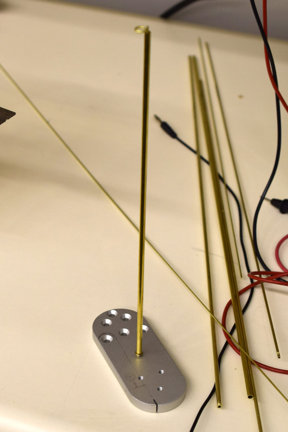
One of the longer brass feet with aluminum assembly jig
I made the feet using nested brass tube with a solid rod through the middle. At the bottom I bent the solid rod into a foot shape. At the top I inserted the small amount of rod that extended past the nested tubes into a hole I drilled into the flat head of some of the brass screws I used to assemble the lamps. With all of this soldered together I could thread three feet into the bottom of each lamp, where they would take the place of some of the assembly screws that would otherwise be necessary. Then I could solder lamp cord to two of the feet per lamp to carry power and ground to the circuits.
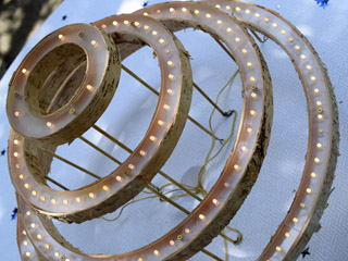
Birch Bark Sides
To finish up the lamps I needed to cover the sides in some suitable material. Birch bark is flexible, easily cut, and makes reference to my family's northern roots and design sense. Applying it to the inside and outside of the acrylic rings meant cutting one inch wide strips and glueing them to the edge of the bottom acrylic ring with cyanoacrylate glue. The top acrylic ring would sit in the birch bark hoops without being glued, so that the lamps could be disassembled.
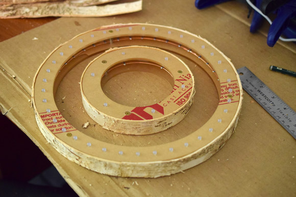
Birch bark added to the outside of the two smallest rings
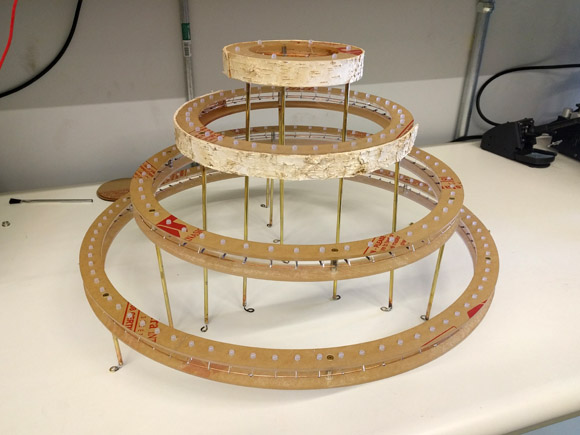
Starting to add the birch bark, with all the lamps arranged together
I'd glue the strips to the rings by starting at one end, adding a line of CA glue an inch or two long to the acrylic edge, clamping a little more of the bark strip, and progressing in this way until I reached the beginning or the 20-inch long strip ran out. For the larger rings I'd have to use more than one strip, carefully trimmed and butt-jointed together to try to make it as seamless as possible.
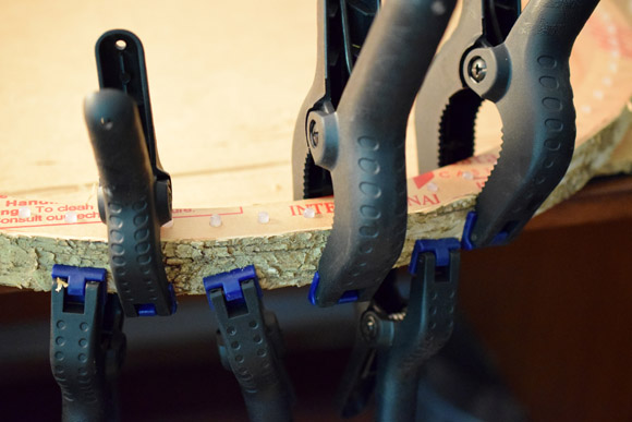
You can never have too many clamps.
With birch bark glued to both the outside and inside of the ring I used a X-acto knife to trim the bark flush. Then I'd connect a 3.3 volt switch-mode wall-wart style power supply to an inline rocker switch, then to the lamp cord via a barrel jack.
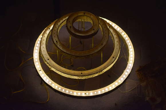
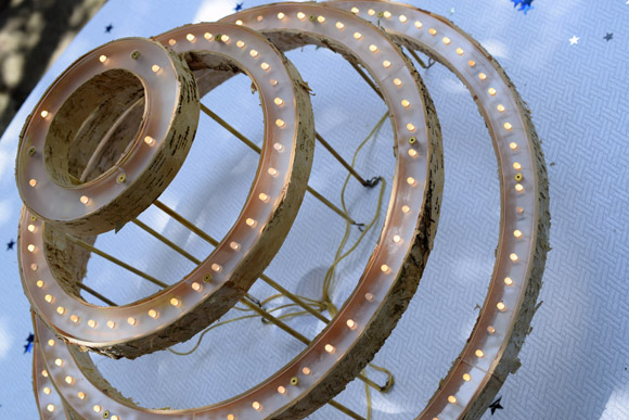
Testing the results the night before the party
A Long-Expected Party
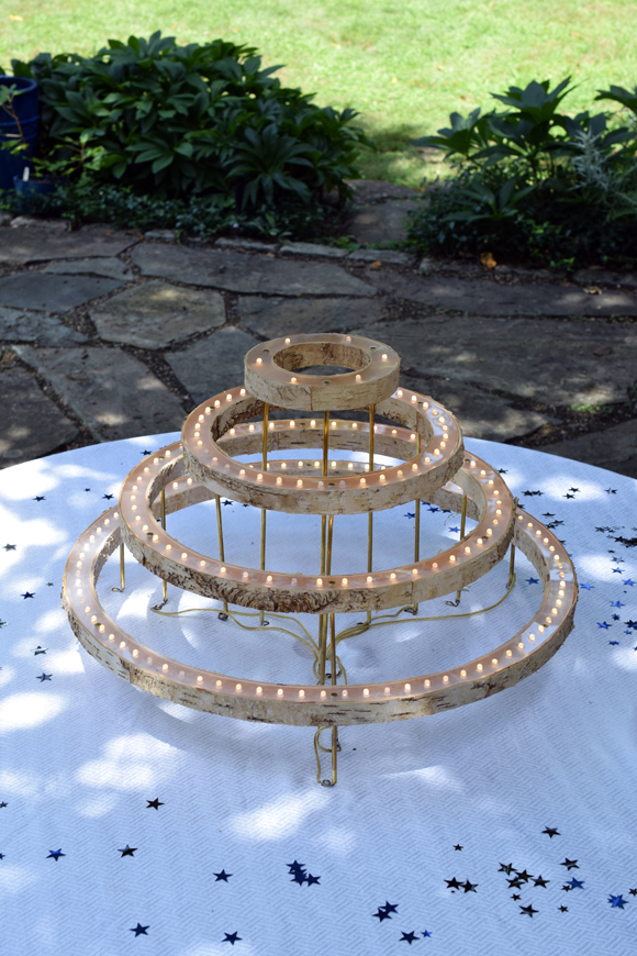
When the morning of the party arrived I went outside and installed the entire assembly on a table in the garden. Each unit could be individually switched off by the birthday kid in question so the candles could be “blown out” as tradition expects. As is also traditional, it eventually started raining and we carried the whole table inside for the cake and the ceremony! But I still managed to first get photos and video of the project in its lovely backyard setting. Enjoy!